


I’ve owned my beloved Canon T2i for six years and resisted upgrading all this time because the sensor remained virtually unchanged with each new model iteration. Canon finally reached parity with competing Nikon DSLRs by featuring a 24 MP APS-C sensor in the new T6i/T6s model. But the Nikon D5500 still retained an important edge, it produced images that were clearly sharper and better resolved than those from the T6i. The reason for this is simple. Nikon decided not to include an anti aliasing (AA) filter, also referred to as an optical low pass filter (OLPF) in the D5500. This is a filter designed to introduce a degree of blurring to the image formed on the sensor.
Aliasing refers to errors in reconstructing the image from sensor data where two distinct signals are represented as equal, or as an alias of the other. This error occurs most commonly in color reconstruction because the nature of the RGB Bayer layer does not allow each pixel to record true color data, rather color values of each pixel are interpolated mathematically by looking at the color data of neighboring pixels. A camera without an OLPF can also exhibit moiré patterns – strange rings or waves of rippling tone and color (or sometimes just color moirés) when photographing objects with highly repetitive patterns of fine detail like those found in textiles or fabrics. The moiré effect is the result of an interference pattern formed from aliasing errors primarily because the highly repetitive source pattern is being spatially undersampled. In other words the true frequency of the source pattern is not being accurately recorded because there are not enough pixels to represent it. You in fact need to sample at twice the frequency of the source pattern to eliminate moiré patterns but since that is not possible, camera engineers found a workaround solution by reducing the source frequency itself with an OLPF and blurring the source image. Color moirés are even more common since color data is severely undersampled as compared to luminance/detail data since the nature of the Bayer layer allows only one in four pixels to be either red or blue. Moiré formation is also exacerbated by the regular grid like nature of the Bayer layer. Moirés were much less common in film since the grains of silver are irregularly and randomly ordered and Fuji’s X-Trans sensor design incorporates a more random distribution of RGB pixels for this reason.
Moirés were much more prevalent in the old days of single digit megapixel sensors, but as pixel density grows with each new generation of cameras, undersampling becomes less of an issue. Pixel density is now approaching or exceeding the diffraction limited resolving power of the camera lens itself at certain apertures. The need for an OLPF is becoming less and Canon now offers the 5DS R, a 51 MP full frame sensor with a self cancelling OLPF.
Since I don’t earn a living through photography, I am compelled to buy the least expensive camera bodies and slowly acquire the best lenses – from the second hand market. This also makes good environmental sense in terms of conserving resources. But I also don’t want to cast an envious glare at my Nikonista friends with their maximally resolving cameras. There are companies that will remove the OLPF from your camera (http://www.maxmax.com/hot_rod_visible.htm) but they charge $450 USD and that is exactly what I paid for my lightly used T6i from eBay. In this article, I’m going to show you how you how you can do it yourself for under $100.
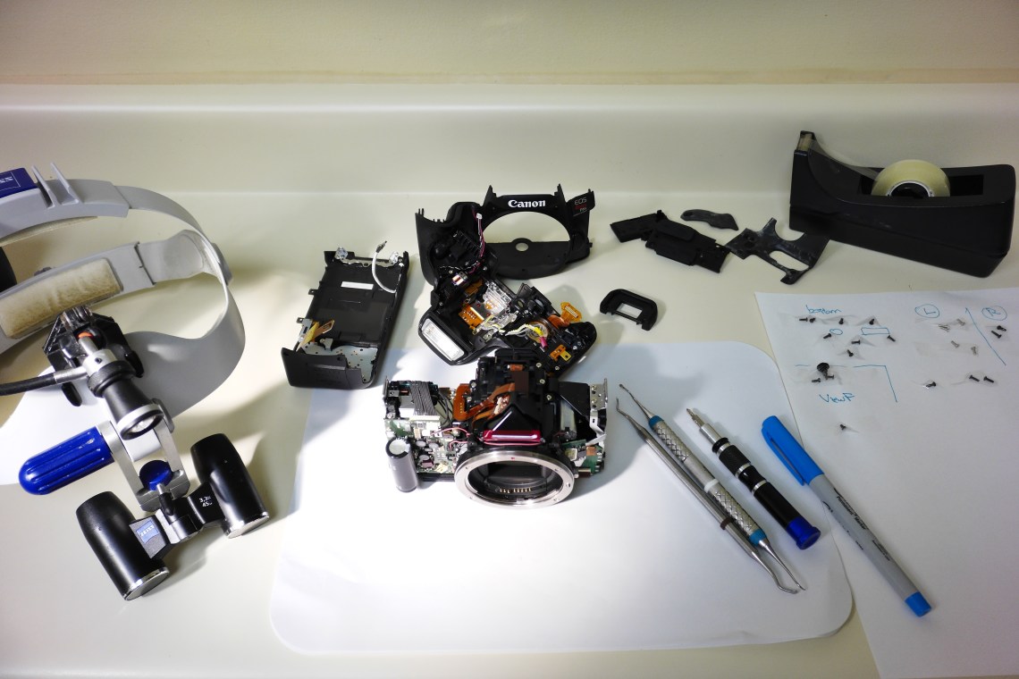
I would like to emphasize that you will be performing real surgery on your camera, and all the imagery that conveys. It is not for everyone, but you don’t need to be an actual surgeon either. There are very detailed tutorials available online (https://www.lifepixel.com/tutorials/infrared-diy-tutorials) that show how to disassemble Canon bodies since we need to ultimately extract the sensor assembly itself. You need a clean and well lit working area, a good set of screwdrivers with a variety of Phillips and Torx heads, tweezers, a digital micrometer, a magnifying glass or set of loupes, and time and patience. A can of compressed air and a box of surgical gloves are very helpful. And like all surgeons you personally need to be well rested and relaxed. Don’t forget to remove the battery and SD card. Don’t touch the large black capacitor in the front of the camera which powers the flash, it will give you a nasty high voltage shock.
Currently, the Life Pixel tutorials are available for the T6s but this model is very similar to the T6i. The only difference is that in Step 12, instead of removing the underside screw over the left corner of the camera to free the top panel containing the rotary dials and viewfinder, the screw is on the top in the T6i. There are also two cables that must be disconnected from the front facing camera circuit board before the top panel can be removed.
The most sensitive procedure involves the remove of the flat flexible cables (FFC) from their sockets. Some cables have reinforced perforations that you can use as a purchase to pull the cables from their sockets. Some sockets have a hinged latch that must be opened before the cable can be safely removed and most latches are clearly visible by being cast in a contrasting color. The FFC socket next to the leftmost socket in the lower left hand corner of the main camera circuit board has a latch that is the same color as the socket and hence almost invisible. If the cable does not come free with minimal force, then beware! It goes without saying that damaging any of these cables is terminal for your camera.
 The many small Phillips machine screws can be organized by being securely taped to a piece of paper with illustrations to show which screws belong to which holes. It’s important to use the correct sized Phillips screwdiver, an undersized head will tend to strip the screw causing undue frustration.
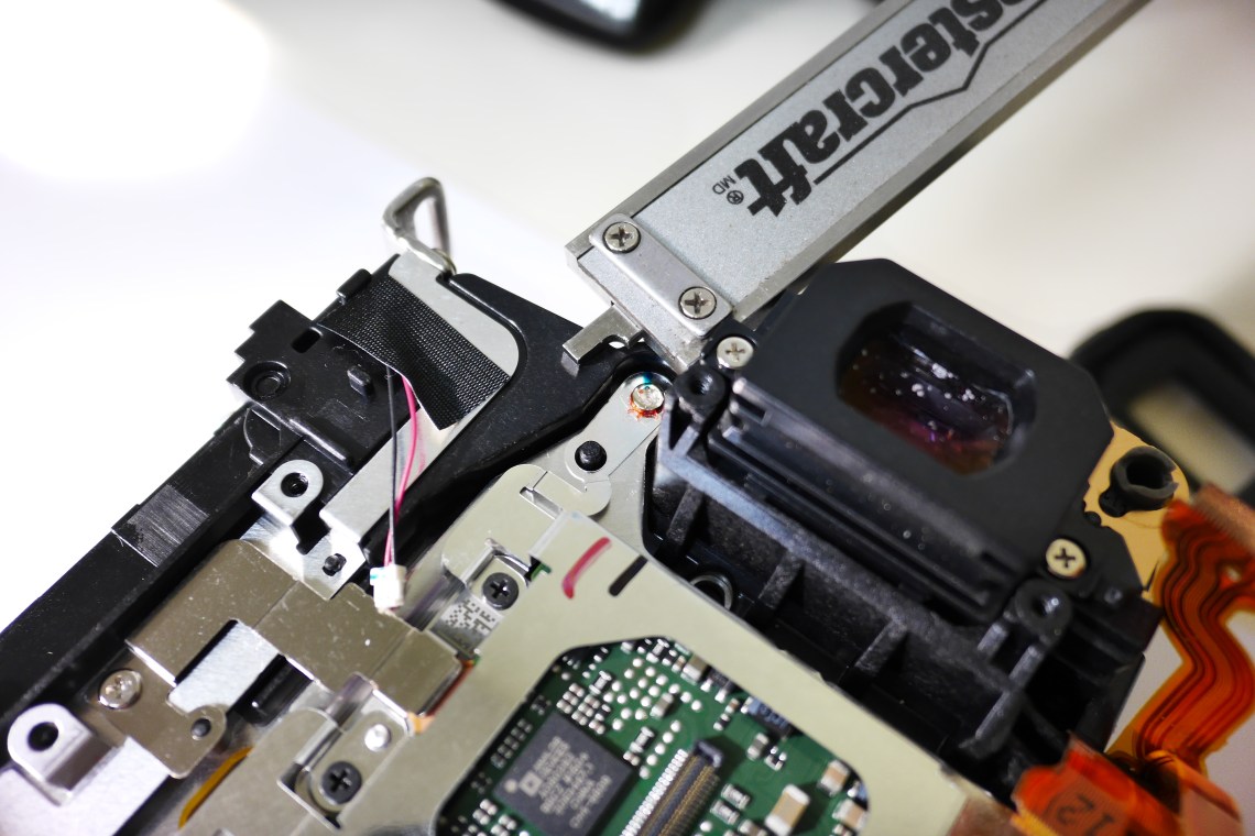
In Life Pixel T6S tutorial step 14, remove the excess glue over the heads of the three T-7 Torx screws and carefully measure the distance between the top of the black plastic guide pins and the metal surface of the sensor assembly with a digital micrometer to a hundreth of a millimeter accuracy. The Torx screws are spring loaded and finely calibrate the position and plane of the sensor relative to the lens mount flange, crucial for attaining sharply focused images. The heads of these screws can also be marked with ink to roughly confirm their original position when they are screwed back in but the micrometer measurements are much more accurate in determining this.
 Once the sensor assembly is freed, the black plastic filter housing is separated from the sensor circuit board by four screws. A metal snap on frame holds the first OLPF (OLPF-1) which separates images in the horizontal direction. Since this piece of glass is also exposed to the exterior, it is attached to a piezoelectric element that gives it self cleaning ultrasonic dust shaking properties. Flipping the black plastic housing upside down reveals an aquamarine filter that is glued in two corners with silicone adhesive. The glue is cut and the filter is removed to reveal a thin strip of double sided tape at its periphery. This is the infrared (IR) blocking filter bonded in the back to the second OLPF which separates the image in the vertical direction. It is also bonded in the front to a phaser layer that converts linear polarized light into circular polarized light.
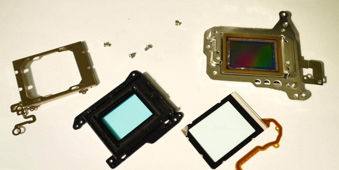 All pieces of original Canon glass are discarded and an optically polished and multicoated piece of glass sourced from Astronomik (MC Klarglass, http://www.astronomik.com) and custom cut to fit the black filter housing precisely. I prefer to place the new glass in place of OLPF-1 as it can be retained by the metal snap on frame without need of adhesive. Just be aware that the lower left corner of the glass needs to be clipped or sanded to allow it to fully drop into its recess and prevent cracking the glass when the metal frame is snapped on.
The sensor assembly is returned to its place in the camera and the three Torx screws returned to their original positions by confirming the measured heights of the black plastic guide pins and the screw head ink markings. Since the MC Klarglass is a little thinner (about 0.4 mm) than the combined thickness of all the Canon glass and there may be also a disparity in the refractive indices of the glass, the image will form slightly ahead of the original position of the sensor, closer towards the lens flange. After several trials, I determined that the Torx screws need to be turned between one quarter and one third clockwise to advance the sensor to the correct position. This is performed to ensure that the phase detect autofocus system in the viewfinder is still accurate.
It’s important to be able to test the accuracy of your autofocus in order to determine what direction to move the sensor and by how much. I had to disassemble the camera four times to make my adjustments until I was satisfied and each time risking damage to the FFC. I was greeted with Error 30, a completely dead camera, and a camera that would not energize the lens – all because of improperly seated FFC. You will experience Error 6 from time to time as the camera is now no longer able to self clean but it is a benign error.
Focus target charts can be downloaded (http://www.gpsinformation.org/jack/iso-gd-cb-955s.jpg) to assess autofocus accuracy. To determine whether your camera is now front or back focusing (typically after this modification the camera will be front focusing) an additional chart can be found here (http://www.kscameraclub.org/docs/pdfs /focus_ test_chart_edited.pdf) with instructions.
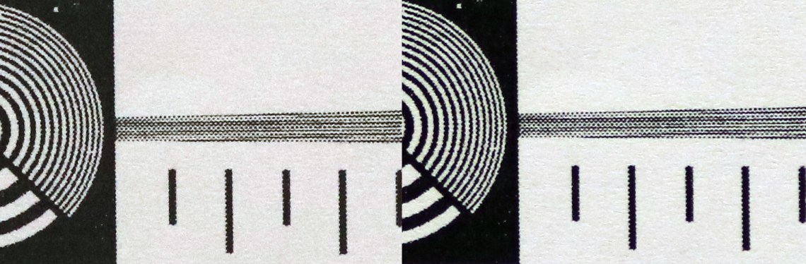
 The above figure shows a central crop of the focus target chart shot with 200 mm f/2.8 L series prime lens at f/2.8 and ISO 400 on a tripod with a Manfrotto 410 head. From left to right is stock T6i, T6i after modification, T6i after 4th sensor position adjustment.
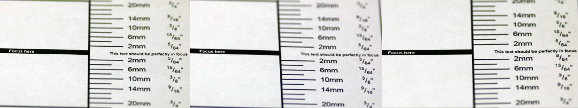 This figure is shot with the second chart placed flat on the floor and the camera angled precisely at 45o with the Manfrotto 410 geared head. From left to right: stock T6i, modified T6i, and modified T6i after 4th adjustment. You can see directly after modification, the T6i is front focusing and the sensor position needs to be moved forward. This ability is possible in higher end Canon bodies and adjusted from the menu.
Since the T6i also features live view on sensor contrast detect focusing, you can compare the sharpness attained with that image with one obtained with conventional phase detect focusing through viewfinder to see if your adjustments are correct. Left is on sensor focus and right is viewfinder focus.
And there you have it, resolution unleashed in your Canon T6i. To obtain normal white balance, Astronomik also sells the OWB Clip In filter that fits by friction just inside the lens flange. This modification also allows the camera to be used for astrophotography since the improved IR response makes it particular sensitive to the hydrogen emissions of certain nebulae. The camera can also be used for true IR photography and Astronomik also markets a variety of IR pass clip in filters.

I just added this site to my google reader, great stuff. Cannot get enough!
LikeLike
You are a brave man! This is an impressive project.
LikeLike